
Case Studies
Case List
- CBN First Financial G01 Studio Network Management System
- Mianyang Radio and Television facility-wide monitoring system
- Guangdong Radio and Television (GRT) intelligent Master Control Room (MCR) --- visual matrix switching system
- Nanjing TV studio source naming system
- Sichuan satellite uplink vehicle satellite system monitoring
- Sichuan TV facility-wide Tally system
- Xiamen TV HD OB Van system
- Yiwu TV Studio Complex UMD&Tally System
- Canxing (Shanghai Canxing Culture Media) 6-Channel Studio Compact Tally System
- Hunan TV integrated network management system
- CCTV new headquarters E14 studio complex monitoring system
- Five Star Sports Channel "Yi Qi Shua Da Pai" Program iStudio System


CCTV new headquarters E14 studio complex monitoring system
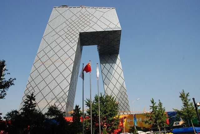
China Central Television (CCTV)
1. Project Background
The studios in the new CCTV building all adopt a cluster design. The E14 and E01 studio clusters are notable for their comprehensive production capabilities.
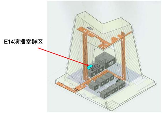
Figure 1: Location and composition of the E14 studio cluster
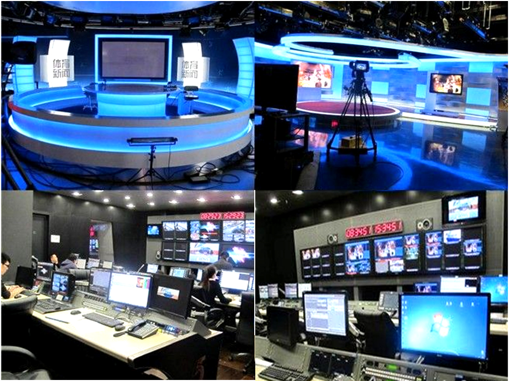
Figure 2: E14 studio cluster
The E14 studio cluster includes a live virtual studio E14 (250 sqm) for sports event broadcasting, a studio E15 (250 sqm) for sports feature production, and an open-plan studio E17 for news production. The studio cluster has a total of 4+3+3 camera channels. Camera channels can be shared across studios, with each studio supporting a maximum of 4 channels.
The studio cluster shares a single 64x64 Matrix, uses file-based media recording and playback tightly coupled with the mixing island for efficient cycling and easy maintenance. Each studio has an HD Switcher with 4 camera input channels for flexible camera assignment. Shared control room camera monitoring is configured for maximum capacity.
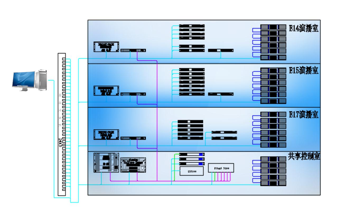 Figure 3: Network topology of the E14 studio cluster Monitoring System
II. E14 Studio Cluster Monitoring System Functions
Device configuration, including Switcher, peripherals, Matrix, etc.:Device parameter settings can be protected based on OnAir status information.
Device and signal status inspection, aggregation of device alarms and Signal Monitoring alarms, and alarm processing:Executes comprehensive alarm processing rules, analyzes alarm causes, achieves precise fault localization, and generates alarm processing results and alarm logs. Provides a recommended solution list and alerts through audible, visual, and electronic means.
Comprehensive management functions.
Interface adaptation with upper-level Monitoring System, submitting status information:A URM adapter is provided as a Software Module of the Monitoring System to enable communication and bridging between the basic Monitoring Module and the station-wide monitoring system.
 Figure 4: Monitoring of diverse equipment types
Monitored devices include:
KHD200C Switcher
Leitch PLATINUM Matrix
6800+ Series peripheral Module Card
LV5800 HD digital waveform monitor
KALEIDO-ALTO-HD multiviewer
KALEIDO-QUAD-HD multiviewer
III. Main/Backup Signal Consistency Alarm
Background: During live broadcasts, the studio must ensure that the Matrix emergency switching signal and the Switcher main channel signal remain consistent. During operation, the emergency signal may be switched away for signal testing. To prevent the broadcast signal from not being restored in time before going live, CCTV requested a monitoring alarm for the emergency channel. An audible and visual alarm is triggered when the emergency signal does not match the Switcher main channel, and the alarm is cleared when the emergency signal is switched back to match the Switcher main channel.
This Function is an upgrade to the existing Monitoring System and operational system. To avoid impacting the existing system, crosspoint information is obtained from the Tally system. The software compares current crosspoint information with preset crosspoint information in the Monitoring System. When a crosspoint changes, an alarm indicator is triggered if the current crosspoint differs from the preset; the alarm indicator is turned off if they match.
The alarm indicator is triggered via GPI and supports long-distance transmission. The indicators in all three studios of the studio cluster are controlled centrally through GPO devices in the equipment room.
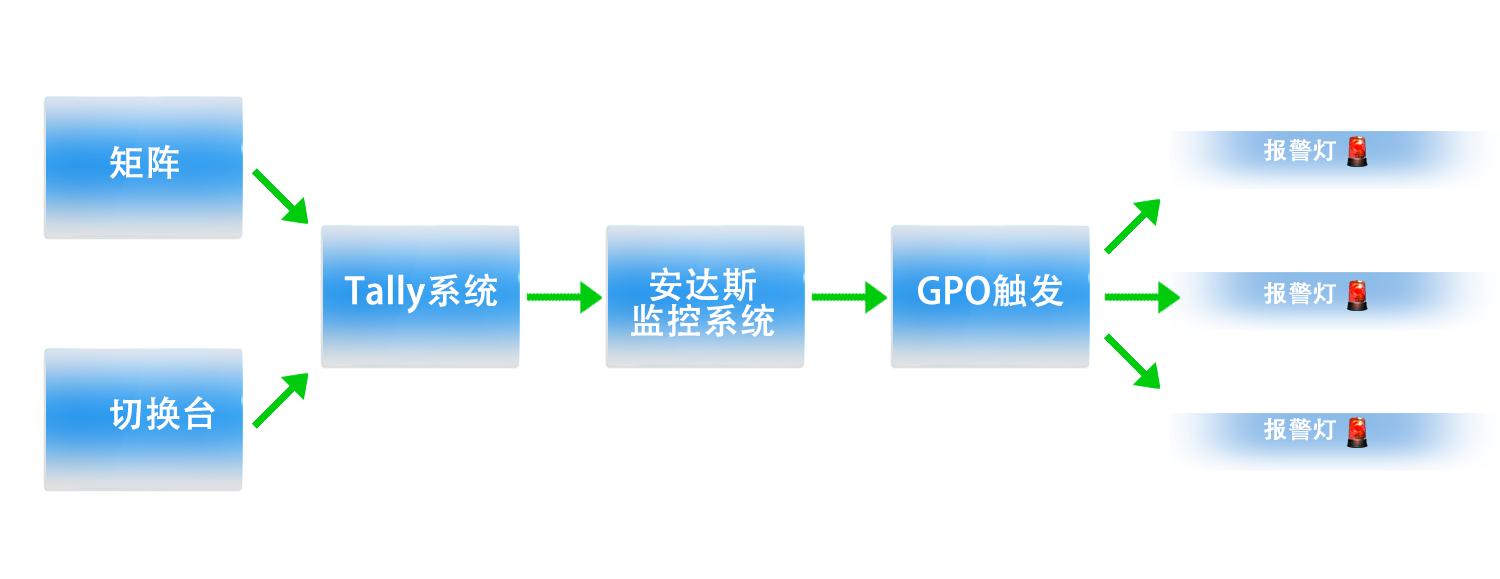 Figure 5: Main/backup out-of-sync alarm
IV. URM Interaction
A key feature of the monitoring component in this project is that the studio cluster Monitoring System must be integrated into the station-wide monitoring system as a level-2 monitoring subsystem.
Data exchanged between the E14 cluster Monitoring System and the URM system is transmitted via the ESB system. This system is primarily responsible for collecting relevant data from the monitored systems within the studio cluster. URM retrieves the collected data from this system through ESB. Architecturally, a dedicated module handles interaction with the URM system, following the URM standard specification.
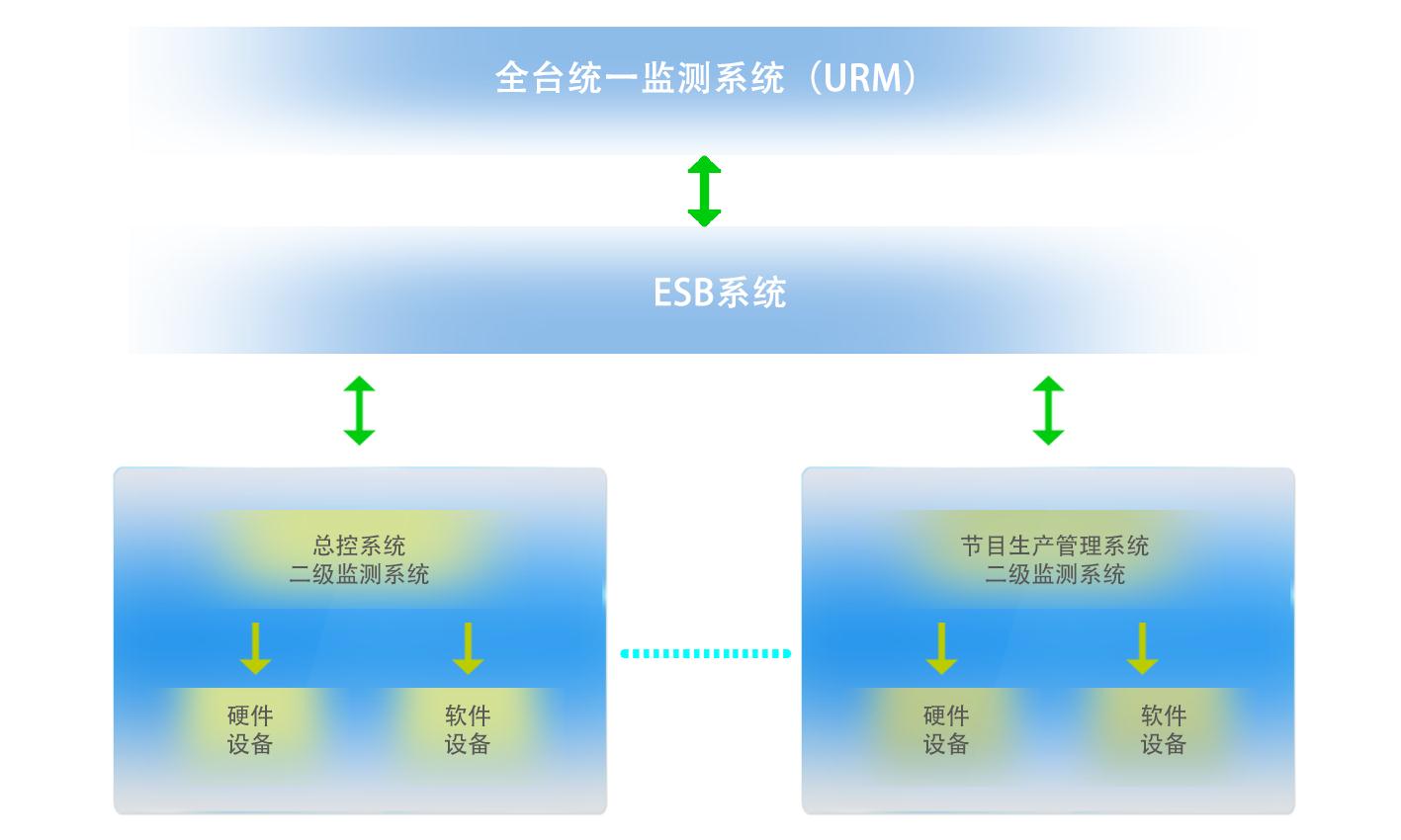 Figure 6: Studio cluster Monitoring System serves as a level-2 monitoring subsystem, interacting and exchanging information with URM
The Monitoring System is a functionally independent product that also provides external interfaces for interaction with upper-level monitoring systems, laying the foundation for building a unified cross-system monitoring infrastructure.
In this project, we developed a URM adapter module for CCTV's station-wide URM monitoring system, serving as a relay and coordinator between the level-2 Monitoring System and the top-level URM. This approach isolates project-specific URM adaptation requirements from the Software Products themselves, preserving product independence and stability.
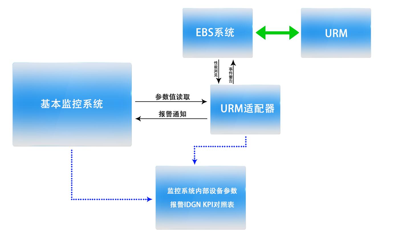 Figure 7: URM adapter module, serving as a relay and coordinator between the level-2 Monitoring System and the top-level URM
V. Signal Inspection Overview
For program production systems such as studios, high-quality broadcast output is always a key concern. Signal Monitoring metrics from Audio/Video Processing equipment such as matrices and peripherals alone are often insufficient. Users typically need more quantitative information beyond basic parameters like signal continuity and loss to achieve system calibration and high-quality broadcast output.
This means introducing the concept of technical signal inspection, using dedicated signal test instruments to perform high-quality signal testing and monitoring for signal quality monitoring and alarming.
In this project, the Leader LV5800 was selected as the signal inspection instrument. Signals of interest are routed to the test instrument through Matrix signal scheduling.
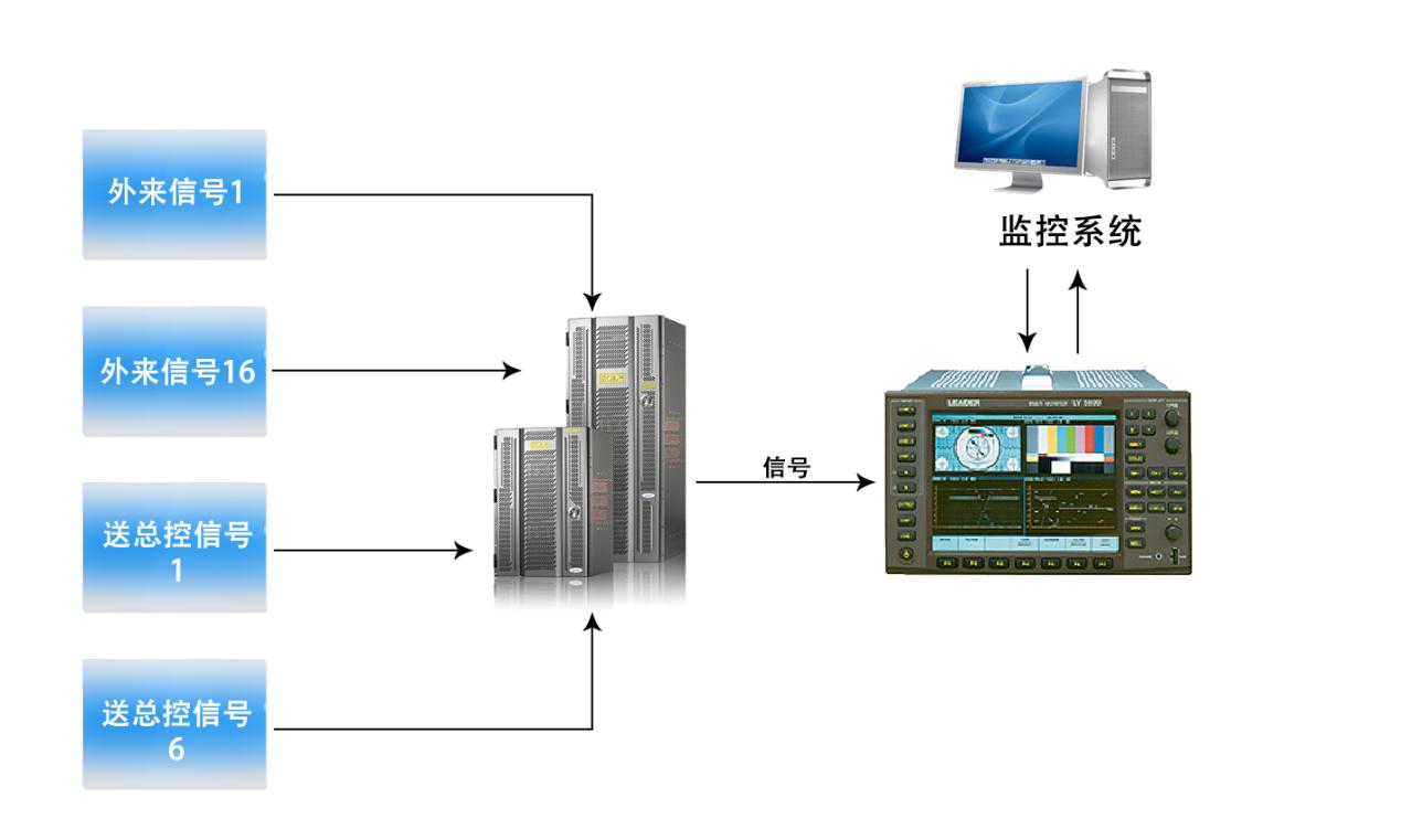 Figure 8: Concept of technical signal inspection in the Monitoring System
Signal inspection scheduling plan:
Signals under inspection are scheduled by a dedicated N*1 signal selector switch.
The signal to master control and other key point signals are distributed and routed to the signal selector switch.
The output of the signal selector switch connects to the waveform monitor input channel. The signal inspection software performs signal parameter testing through the waveform monitor.
The monitoring computer connects to the test instrument via a network port and to the Matrix via a serial port. The software switches the Matrix to automatically schedule signals into the waveform monitor.
The inspection process involves sending a switching command to the Matrix to route the designated signal to the waveform monitor, then sending a command to the waveform monitor to execute a specific parameter test, and finally collecting and analyzing the test results. If anomalies are detected, an alarm is raised.
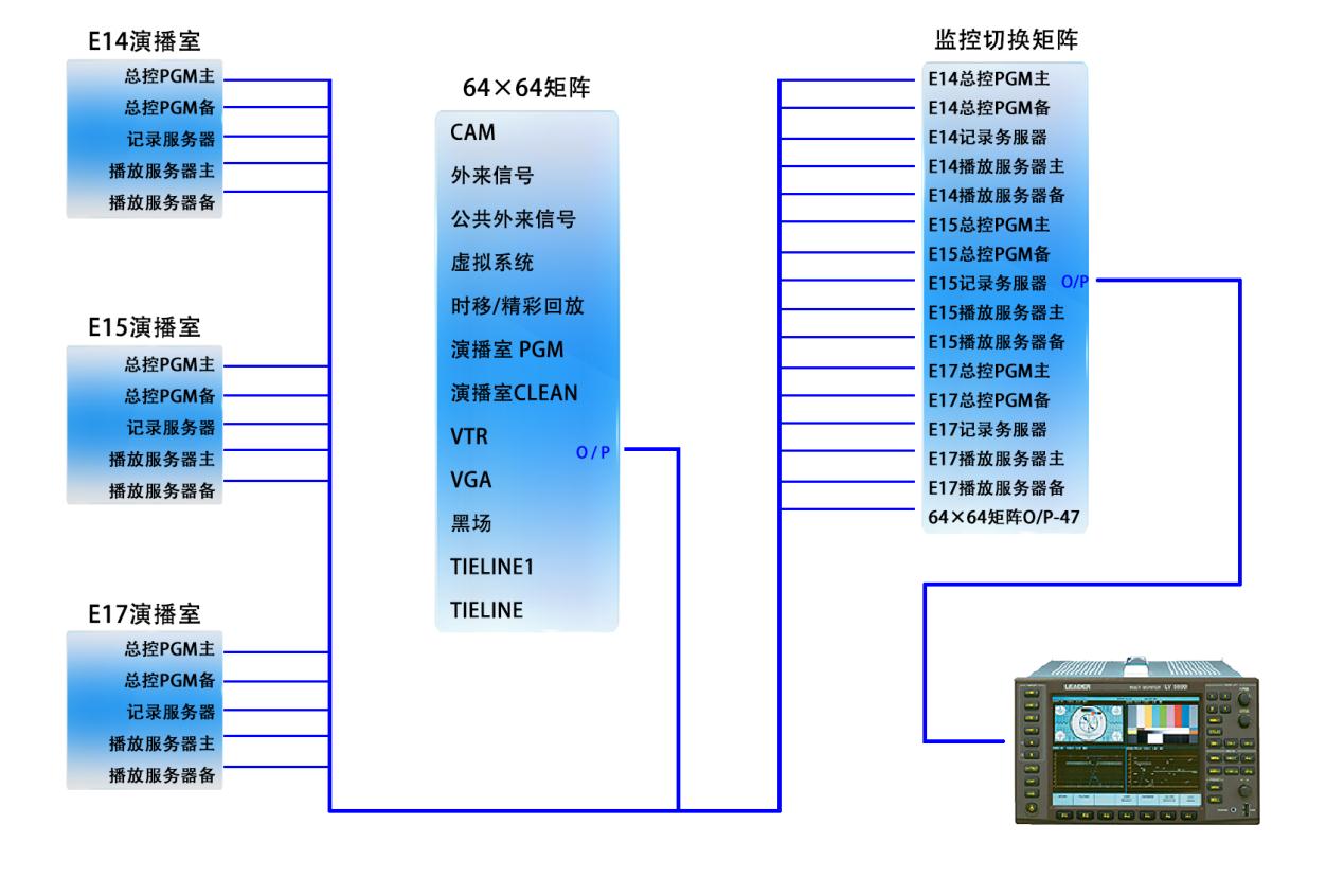 Figure 9: Signal selection scheme for technical signal inspection in the E14 studio cluster Monitoring System
VI. Project Timeline and Operational Results
The E14 studio cluster project completed system commissioning and testing from 2009 to 2011, and was delivered along with the studio cluster in 2012. It has been running stably since then.
The URM interaction and station-wide monitoring system integration, joint commissioning, and testing began in early 2013. It was successfully deployed and put into operation by the end of 2013 and has been running stably since.
As one of the most important auxiliary systems, the Monitoring System safeguards safe and high-quality broadcast output for CCTV's studio cluster.